冷启动条件下的LED驱动器设计
Design of LED Drivers under the Cold Crank Condition
美国国家半导体公司LK Wong, TK Man
简介
近年来,采用LED灯串为汽车提供LCD面板背光越来越普遍。使用LED的好处包括快速的响应时间、更高的对比度和更低的功耗。控制LED灯串的LED驱动器一般由汽车电池供电,为简化LED的光学和散热设计,每个灯串中的LED数量一般不多于6个。对于标称电压为12V的电池,带有线性稳流器的升压转换器(如图1)可实现此功能。
IntroductionThe application of LED strings for providing LCD panel backlight in automotive becomes popular in recent years. The advantages of using LEDs include fast response time, high contrast ratio, and low power consumption. The LED driver controlling the LED strings is powered by the battery of vehicles. To easy the design of optics and heat sink for the LEDs, the number of LEDs in each string is normally more than 6. For a battery with a nominal voltage of 12V, a boost converter with a linear current regulator (as shown in Fig. 1) can be empolyed to perform the function.
冷启动条件
在汽车应用中电池电压会发生改变。通常,一个12V电池,其电压会在9V到16V之间变化。因此,汽车电池供电的电路在设计时均应考虑输入电压的变化情况。此外,如果考虑冷启动条件,对于15ms左右较短的持续时间,最坏情况下,电池电压将低至3V±0.2V,如2.8V。而后电池电压升到6V,并持续数秒,在数秒的上升时间内将恢复到标称电压范围内。冷启动条件下的电池电压曲线与之类似,但不同汽车制造商所提供的产品的电平和变化/持续时间会有所不同。图2给出了典型示例。冷启动可能发生在汽车负载突降及低温环境下。尽管冷启动持续时间不长,但仍需确保LCD面板和安全电子部件等重要的汽车组件以保证正常运行。
Cold crank conditionVariation of the battery voltage is common in automotive. Normally, for a 12V battery, the battery voltage varies from 9V to 16V. Therefore all circuits powered by the battery of vehicles should be designed to take care of the input voltage variation. Furthermore, if a cold crank condition is to be considered, the battery voltage can be down to 3V±0.2V, i.e. 2.8V for the worst case, for a short duration of around 15 ms. Then the battery voltage goes up to 6V and last for few seconds, before resuming to the nominal voltage range at a rise time of few seconds. The battery voltage profile for a cold crank condition is similar, but the voltage level and timing may be different for different automotive manufacturers. One typical example is shown in Fig. 2. The cold crank condition may happen at load dump of vehicles and at a low temperature. Although the duration of the condition is not long, important automotive equipment like LCD panels, safety electronics are required to maintain normal operation.
设计考量
考虑到冷启动条件,在设计LED驱动器时需要强大的升压转换器。参看图1,电池电压的变化仅会影响升压转换器,如果升压转换器可以在冷启动条件下保持输出电压,那么线性稳流器的工作就不受影响,LED灯串的亮度也会保持不变。由于冷启动条件下的输入电压值极低,因此设计时还需要考虑一些其他因素,包括:
Design considerationTo design LED drivers with the consideration of the cold crank condition, a robust boost converter is required. Refer to Fig. 1, the variation of the battery voltage affects only the boost converter. If the boost converter can maintain the output voltage under the cold crank condition, the operation of the linear current regulator is not affected, and therefore the luminance of the LED strings remains unchanged. Since the input voltage is very low under the cold crank condition, there are some extra design considerations, as stated in the following.
升压控制器工作范围
理论上说,只要没有达到占空比的上限,升压转换器(而非升压控制器)的输入电压可以设置的很低,但是“升压控制器”(通常是一个IC芯片)的工作电压则有一个更低的下限值。大部分升压控制器的工作电压不得低于3V。不过如前所述,在冷启动时,最坏情况下电池电压可以低至2.8V,令升压控制器工作(而不是上电即可)在低输入电压下的常规方法以双电源路径为升压控制器供电,包括电池电压和升压转换器的输出电压,通过二极管回连到升压控制器的输入端子(如图3)。此类情况下,在上电过程中“升压控制器”由电池供电,之后则由升压转换器的输出进行供电。这样,只要升压转换器可以提供正常的输出电压,输入电压的压降就不会影响升压控制器的工作。
Operating range of boost controllerTheoretically, the input voltage of a boost converter (not boost controller) can be low provided that the upper limit of the duty ratio is not reached. However, the operating voltage of a “Boost Controller” (usually an IC) has a lower limit. Most boost controllers cannot operate at an input voltage lower than 3V. But under the cold crank condition, the battery voltage can be down to 2.8V in the worst case as memtioned in before. A conventional method to enable a boost controller to operate (not power-up) at low input voltage is to power the boost controller by dual power supply paths, which include the battery voltage and the output voltage of the boost converter, connecting back to the input terminal of the boost controller through diodes as shown in Fig. 3. In this case, the “Boost Controller” is powered by the battery during power-up; and by the output of the boost converter afterward. Then the drop of the input voltage no longer affects the operation of the boost controller as long as the boost converter can provide a normal output voltage.
输入电流
LED灯串的亮度和升压转换器的输出功率需要保持不变,所以,输入电流会随着输入电压的减小而增大。这即意味着在冷启动条件下,电感器和MOSFET开关的峰值电流都要远大于正常工作下的值(当电池电压降在标称范围内时)。例如,电池电压为3V时其输入电流大约是12V时的4倍。所以在选择时,电感器需要有更大的饱和电流,而MOSFET开关需要承受更高的导通电流。
Input currentIf the luminance of LED strings is required to remain unchanged, the output power of the boost converter must be maintained, and as a result, the input current increases with the decrease of the input voltage. This implies that under the cold crank condition the peak inductor and MOSFET switch currents are much larger as compared with nominal operation (when the battery voltage falls in the nominal range). For example, the input current at a battery voltage of 3V is about 4 times of the input current at a battery voltage of 12V. Hence, inductors with larger saturation current and MOSFET switches that can withstand higher turn-on current should be selected.
热管理
冷启动条件下,MOSFET开关的电流和占空比都要大于标称工作时的值,这意味着MOSFET开关的传导损耗会大幅增加。尽管冷启动条件的持续时间很短,但MOSFET开关的温度会大幅上升。如果MOSFET开关集成在升压控制器IC 内,为了使元件数量和解决方案尺寸最小化,那么有效的散热方案就非常重要,因为不佳的热管理会触发IC芯片的热保护电路,使LED意外断电。
Thermal managementUnder the cold crank condition, not only the current but also the duty ratio of the MOSFET switch is larger than nominal operation. This implies a drastically increase in the conduction loss of the MOSFET switch. Although the duration of the cold crank condition is short, significant temperature rise in the MOSFET switch can appear. If the MOSFET switch is integrated in a boost controller IC (owing to minimize component count and solution size), an effective heat dissipation mechanism is critical because poor thermal management may trigger the thermal protection circuit of the integrated circuit and lead to unexpected turn-off of LEDs.
推荐电路
图4展示了考虑到冷启动情况下,汽车中使用的LCD面板背光普遍采用LED驱动器的电路,该电路使用了美国国家半导体的LM3492芯片。该电路驱动2个LED灯串,每个灯串都含有工作电流为100mA的6个LED。电路的标称输入电压范围为9V至16V,标称开关频率为300 kHz。该电路的基本组成元素包括一个升压转换器和一个双通道线性稳流器。MOSFET开关集成在LM3492内,实现了更小的方案体积。LM3492的VIN针脚通过二极管连到输入电压,当电池电压低于最低要求的4.5V时,芯片内部连接了VIN和VOUT引脚(后者连接升压转换器的输出电压)的电路就会为LM3492供电。这里选用了一个饱和电流为3.36A 的33uH电感器,尽管对于正常输入电压而言,1A的饱和电流就已足够。
Proposed circuitA popular LED driver circuit for LCD panel backlight in automotive applications with the consideration of the cold crank condition using the LM3492 from National Semiconductor Corporation is shown in Fig. 4. The circuit drives 2 LED strings, each of which consists of 6 LEDs running at 100 mA. The nominal input voltage of the circuit is ranged from 9V to 16V, and the nominal switching frequency is 300 kHz. Basically, the circuit includes a boost converter and a 2-channel linear current regulator. The MOSFET switch is integrated in the LM3492 so that a small solution size can be achieved. The VIN pin of the LM3492 is connected to the input voltage through a diode. There is an internal circuit connecting the VIN pin from the VOUT pin, which is connected to the output voltage of the boost converter, to power the LM3492 if the battery voltage is lower than the minimum requirement of 4.5V. An inductor of 33uH with a saturation current of 3.36A is selected, although a saturation current of 1A is enough for normal input voltage.
测量结果
图5和图6显示了输入电压为12V(标称值)和2.8V(冷启动时的最坏情况)下LM3492电路的波形。表1总结了LM3492电路工作在标称条件和冷启动条件下的测量结果。可以看到,即使输入电压低至2.8V,LED电流也保持不变,这表示背光亮度并不受冷启动条件影响。从图6的波形可知,输入电压为2.8V时的占空比大于90%,同时还测量了2.61A的大输入电流,如表1所示。为此,其内部MOSFET开关的功率损耗也就相对较大。LM3492外壳上可测得90℃的温升(标称输入电压范围下仅为30℃)。参考表1中的效率可知,冷启动条件下的效率会下降到56%,尽管标称输入电压范围内的效率可高达90%。
Measured resultsFigs. 5-6 show waveforms of the LM3492 circuit when the input voltage is 12V (nominal) and 2.8V (the worst case under the cold crank condition). Table 1 summarizes measured results when the LM3492 circuit operates in the nominal condition and under the cold crank condition. It can be observed that the LED current remains unchanged even when the input voltage is as low as 2.8V, meaning that the luminance of the backlight is not affected by the cold crank condition. From the waveforms of Fig. 6, it is seen that the duty ratio is larger than 90% at 2.8V input voltage. Also, a large input current of 2.61A is measured, as shown in Table 1. Consequently, the power loss in the internal MOSFET switch is large. A temperature rise of 90°C is measured on the case of the LM3492 (only a 30°C temperature rise at the nominal input voltage range). With reference to the efficiency in Table 1, the efficiency drops to 56% under the cold crank condition, although a high efficiency of around 90% can be obtained at the nominal input voltage range.
结论
考虑到汽车应用中的冷启动条件,本文介绍了一款普遍用于LCD面板背光的LED驱动器电路。前面已经讨论了一些特殊设计考虑,包括双电源供电、饱和电流更高的电感器选择和热管理。测量波形显示,LED电流并未受影响,即使输入电压降到2.8V时仍可保证正常工作。在9V至16V的标称输入电压下,可以实现约90%的高效率。
ConclusionWith the consideration of the cold crank condition in automotive applications, this article introduces a popular LED driver circuit for LCD panel backlight. Special design considerations including the dual power supply paths, selection of inductor with a higher saturation current, and thermal management have been discussed. Measured waveforms show that the LED current is not affected and the circuit can maintain normal operation even when the input voltage drops to 2.8V. A high efficiency of around 90% is obtained in the nominal input voltage range of 9V to 16V.
|
输入电压 |
输入电流 |
LED灯串电压 |
LED电流 |
效率 |
|
2.8V |
2.61A |
20.7V |
0.1A /串 |
56.7% |
|
6V |
0.78 |
20.7V |
0.1A /串 |
88.5% |
|
9V |
0.51A |
20.7V |
0.1A /串 |
90.2% |
|
12V |
0.38A |
20.7V |
0.1A /串 |
90.7% |
|
16V |
0.29A |
20.7V |
0.1A /串 |
92.4% |
表1. 测量结果总结

图1.由升压转换器和线性电流调节器组成的LED驱动器
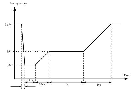
图2. 典型冷启动电池电压曲线
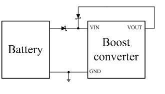
图3. 带双电源供电的升压转换器

图4. 考虑冷启动条件的LM3492参考设计


发表评论 评论 (2 个评论)